Programming
Writing the firmware
- Download and install Arduino IDE (https://www.arduino.cc/en/soft)
- Open file simbox.ino or simbox-no-storage.ino in Arduino IDE (it was downloaded together with STL files)
- Configure Arduino IDE to use ESP board (https://randomnerdtutorials.com/installing-the-esp32-board-in-arduino-ide-windows-instructions/)
- Install ArduinoJSON extension (https://arduinojson.org/v6/doc/installation/)
- Compile project and save it on your board
- Open serial monitor and set baud rate to 115200
- Verify that 'SimBoxPing' is printed in serial monitor
Configuring the ESP board
Make sure that your ESP board is connected to your computer and serial monitor is NOT open.
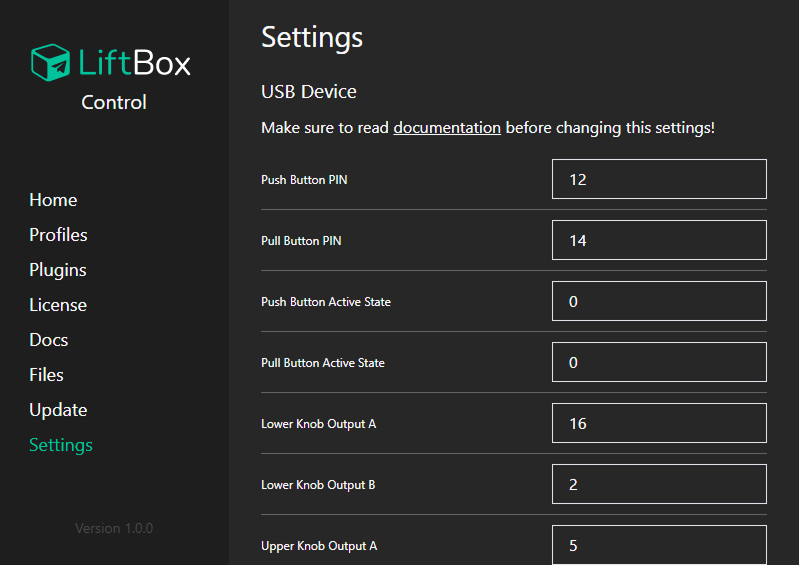
Go to 'Settings' item in control program.

Set proper pin numbers according to your board version. If you use NodeMCU v1 board, and did wiring according to diagram, you can use values as follows:
- Push Button PIN: 12
- Pull Button PIN: 14
- Push Button Active State: 0
- Pull Button Active State: 0
- Lower Knob Output A: 16
- Lower Knob Output B: 2
- Upper Knob Output A: 5
- Upper Knob Output B: 4
- Push Button Minimal Signals: 1000 (determines how many signals are required to trigger push button)
- Pull Button Minimal Signals: 1000 (determines how many signals are required to trigger pull button)
- Upper Knob Mode: 0 (if you'll encounter issues with upper knob, try to change this value to 1)
- Lower Knob Mode: 0 (if you'll encounter issues with lower knob, try to change this value to 1)
- Upper Knob Switch Directions: 0 (if your upper knob is rotating in opposite direction, change this value to 1)
- Lower Knob Switch Directions: 0 (if your lower knob is rotating in opposite direction, change this value to 1)
Click 'Save' button. Board should restart automatically.